OSI Model in Computer Networks
The OSI (Open Systems Interconnection) Model is a conceptual framework used to understand how data is transmitted from one device to another over a network. It divides the communication process into seven distinct layers, where each layer performs a specific function and works with the layers above and below it.
The OSI model helps in standardizing communication functions, making it easier to design, implement, and troubleshoot network systems. Each layer plays an important role in ensuring that data is transferred accurately and efficiently from sender to receiver.
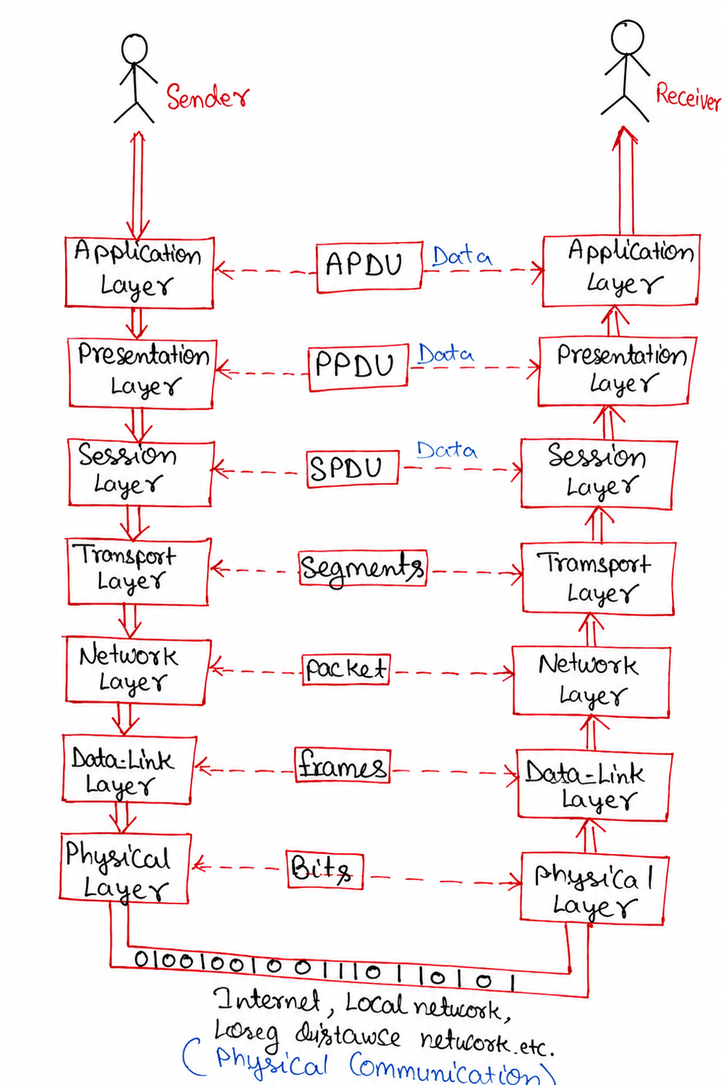
7 Layers of OSI Model
- Application Layer
- Presentation Layer
- Session Layer
- Transport Layer
- Network Layer
- Data Link Layer
- Physical Layer
1. Application Layer
The Application Layer is the highest layer of the OSI Model and acts as a bridge between the user and the network. It allows users to access network services through applications such as web browsers, email clients, and file transfer tools.
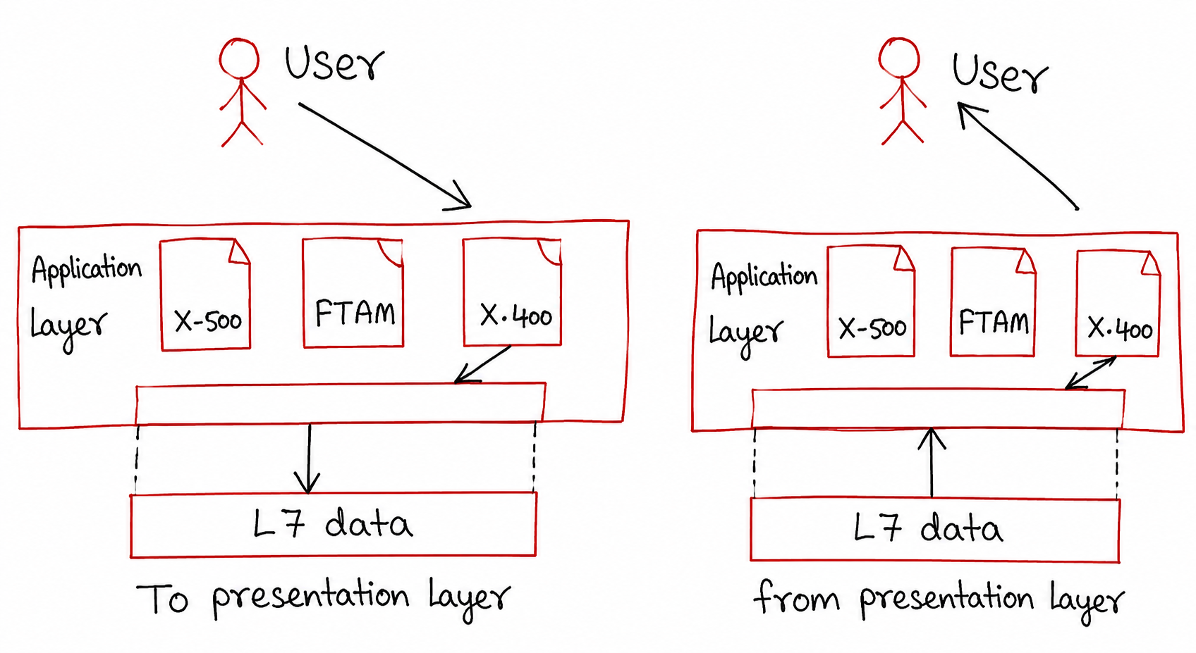
As shown in the diagram, the communication process at the Application Layer happens in two directions: sending data (left side) and receiving data (right side).
Working of Application Layer
Sender Side:
- The user interacts with an application (for example: sending an email or opening a website).
- The Application Layer uses specific protocols like X.500, FTAM, and X.400 depending on the service.
- These protocols prepare and structure the data for communication.
- The data is then called Layer 7 (L7) Data.
- This data is passed to the Presentation Layer for further processing.
Receiver Side:
- The Application Layer receives L7 Data from the Presentation Layer.
- It identifies the correct protocol required to process the incoming data.
- The data is converted into a readable format for the user.
- Finally, the processed data is delivered to the user application.
Functions of Application Layer
- Provides an interface between user and network
- Supports services like email, file transfer, and web browsing
- Ensures communication between different applications
- Handles high-level protocols for data exchange
Common Protocols
- HTTP (Web Browsing)
- FTP (File Transfer)
- SMTP (Email Sending)
2. Presentation Layer
The Presentation Layer is the sixth layer (Layer 6) of the OSI Model and is responsible for data representation, translation, encryption, and compression. It ensures that data sent by the sender can be correctly interpreted by the receiver, regardless of differences in data formats between systems.
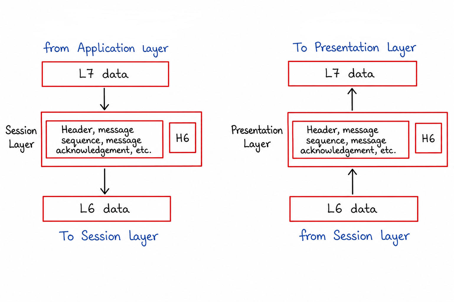
As shown in the diagram, the Presentation Layer processes data in two directions: sending data (left side) and receiving data (right side). It acts as a translator between the Application Layer and the Session Layer.
Working of Presentation Layer
Sender Side:
- The Presentation Layer receives L7 Data from the Application Layer.
- It translates the data into a standard format that can be understood by the receiving system.
- Data can be encrypted to provide security during transmission.
- Data may also be compressed to reduce its size and improve transmission efficiency.
- The layer adds Presentation Layer information (H6 Header) to the data.
- The processed data is then called L6 Data.
- Finally, the data is passed to the Session Layer for further communication.
Receiver Side:
- The Presentation Layer receives L6 Data from the Session Layer.
- It removes the H6 Header added by the sender.
- Compressed data is decompressed back to its original form.
- Encrypted data is decrypted to restore the original information.
- The data format is converted into a form that the receiving application can understand.
- The resulting L7 Data is then passed to the Application Layer.
Functions of Presentation Layer
- Data translation and format conversion
- Data encryption for secure communication
- Data decryption at the receiver side
- Data compression to reduce transmission time
- Data decompression after reception
- Ensures compatibility between different systems
Common Data Formats Handled
- ASCII and Unicode text formats
- JPEG, PNG, and GIF image formats
- MPEG and MP4 video formats
- MP3 and WAV audio formats
3. Session Layer
The Session Layer is the fifth layer (Layer 5) of the OSI Model. It is responsible for creating, managing, and terminating communication sessions between two devices. This layer ensures that communication remains organized and synchronized throughout the data exchange process.
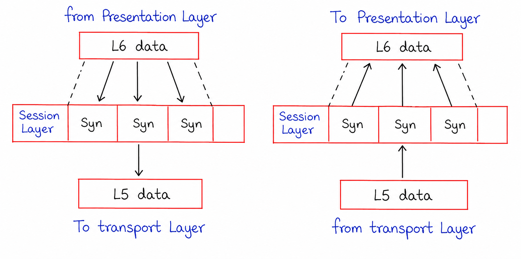
As shown in the diagram, the Session Layer receives data from the Presentation Layer, organizes the communication into synchronized sessions, and forwards it to the Transport Layer. On the receiving side, it restores and manages the session before passing data back to the Presentation Layer.
Working of Session Layer
Sender Side:
- The Session Layer receives L6 Data from the Presentation Layer.
- It establishes a communication session between the sender and receiver.
- The layer inserts synchronization points (Syn) into the data stream.
- These synchronization points act as checkpoints during data transmission.
- If an interruption occurs, communication can resume from the last checkpoint instead of starting again.
- The processed data is then referred to as L5 Data.
- Finally, the data is forwarded to the Transport Layer.
Receiver Side:
- The Session Layer receives L5 Data from the Transport Layer.
- It identifies and manages the active communication session.
- The synchronization points are used to verify the correct sequence of received data.
- If data recovery is required, the session can continue from the nearest checkpoint.
- The layer maintains session control until communication is completed.
- After processing, the data is converted back into L6 Data.
- The data is then passed to the Presentation Layer.
Functions of Session Layer
- Establishes communication sessions between devices
- Maintains and manages active sessions
- Terminates sessions after communication is completed
- Provides synchronization through checkpoints
- Supports recovery from communication failures
- Controls dialog between sender and receiver
Key Features
- Session Establishment: Creates a connection before data transfer begins.
- Session Maintenance: Keeps communication active during data exchange.
- Session Termination: Properly closes the connection after transmission.
- Synchronization: Uses checkpoints to prevent complete retransmission after errors.
Examples of Session Layer Usage
- Video conferencing sessions
- Remote desktop connections
- Online banking sessions
- Database communication sessions
4. Transport Layer
The Transport Layer is the fourth layer (Layer 4) of the OSI Model. It is responsible for providing end-to-end communication between devices on a network. This layer ensures that data is delivered accurately, in the correct order, and without loss whenever reliable communication is required.
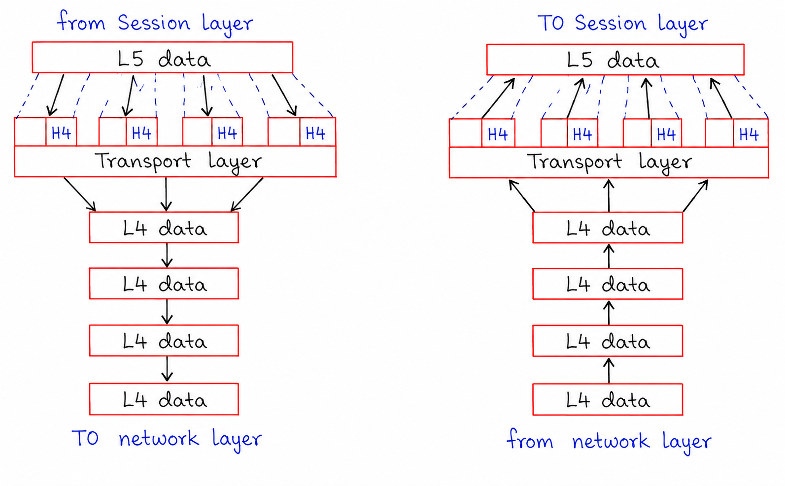
As shown in the diagram, the Transport Layer receives L5 Data from the Session Layer and divides it into smaller units called segments. A Transport Layer header (H4) is added to each segment before forwarding them to the Network Layer. At the receiving side, these segments are reassembled into the original data and delivered to the Session Layer.
Working of Transport Layer
Sender Side:
- The Transport Layer receives L5 Data from the Session Layer.
- Large amounts of data are divided into smaller and manageable segments.
- A Transport Layer Header (H4) is added to each segment.
- The header contains important information such as port numbers, sequence numbers, and control information.
- Each segment is treated as L4 Data.
- The segments are arranged in sequence for proper delivery.
- Finally, the segmented data is passed to the Network Layer.
Receiver Side:
- The Transport Layer receives multiple L4 Data segments from the Network Layer.
- It checks the sequence information stored in each segment.
- Any missing or damaged segments can be identified.
- The segments are reassembled in the correct order.
- The Transport Layer removes the H4 Header from each segment.
- The original L5 Data is reconstructed.
- The reassembled data is then forwarded to the Session Layer.
Functions of Transport Layer
- Provides end-to-end communication between devices
- Performs segmentation and reassembly of data
- Ensures reliable data delivery when required
- Performs error detection and recovery
- Controls data flow between sender and receiver
- Maintains proper sequencing of transmitted data
- Supports multiplexing using port numbers
Key Features
- Segmentation: Breaks large messages into smaller segments for efficient transmission.
- Flow Control: Prevents the sender from overwhelming the receiver with excessive data.
- Error Control: Detects transmission errors and supports retransmission when necessary.
- Sequencing: Ensures data reaches the destination in the correct order.
- Multiplexing: Allows multiple applications to communicate simultaneously using different port numbers.
Common Transport Layer Protocols
- TCP (Transmission Control Protocol): Provides reliable, connection-oriented communication with error recovery and acknowledgment.
- UDP (User Datagram Protocol): Provides faster, connectionless communication with lower overhead.
Examples of Transport Layer Usage
- Web page loading through TCP connections
- Email transmission between mail servers
- Video streaming and online gaming using UDP
- File downloads requiring reliable delivery
5. Network Layer
The Network Layer is the third layer (Layer 3) of the OSI Model. It is responsible for delivering data from the source device to the destination device across one or more interconnected networks. This layer determines the best path for data transmission and ensures that packets reach the correct destination using logical addressing.
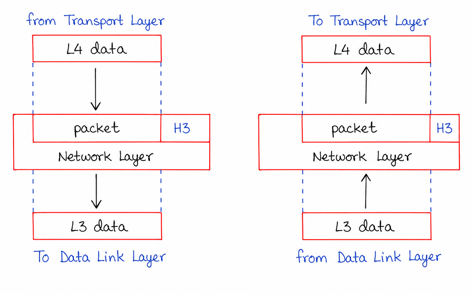
As shown in the diagram, the Network Layer receives L4 Data from the Transport Layer. It adds a Network Layer header (H3) to create a packet and then forwards it to the Data Link Layer. On the receiving side, the header is processed and removed before the original data is passed to the Transport Layer.
Working of Network Layer
Sender Side:
- The Network Layer receives L4 Data from the Transport Layer.
- It adds a Network Layer Header (H3) containing source and destination logical addresses.
- After adding the header, the data unit becomes a Packet.
- The layer determines the most suitable route for packet delivery.
- Packets are prepared for transmission across different networks.
- The resulting L3 Data is forwarded to the Data Link Layer.
Receiver Side:
- The Network Layer receives L3 Data from the Data Link Layer.
- It examines the packet header to verify the destination address.
- The H3 Header is removed after processing.
- The layer confirms that the packet has reached the correct destination.
- The original L4 Data is extracted from the packet.
- The data is then passed to the Transport Layer for further processing.
Functions of Network Layer
- Provides logical addressing using IP addresses
- Determines the best route between source and destination
- Performs packet forwarding across networks
- Handles communication between different network segments
- Supports internetworking and packet delivery
- Manages routing decisions using routing protocols
Key Features
- Logical Addressing: Uses IP addresses to uniquely identify devices on a network.
- Routing: Selects the most efficient path for packet transmission.
- Packet Forwarding: Moves packets from one network device to another until they reach the destination.
- Path Determination: Calculates routes based on network conditions and routing tables.
Common Network Layer Protocols
- IPv4 (Internet Protocol Version 4)
- IPv6 (Internet Protocol Version 6)
- ICMP (Internet Control Message Protocol)
- IGMP (Internet Group Management Protocol)
Devices Operating at Network Layer
- Routers
- Layer 3 Switches
- Multilayer Network Devices
Examples of Network Layer Usage
- Routing internet traffic between different networks
- Sending data from one city or country to another
- Connecting multiple LANs through routers
- Finding the optimal path for packet delivery
6. Data Link Layer
The Data Link Layer is the second layer (Layer 2) of the OSI Model. It is responsible for providing reliable communication between two directly connected devices on the same network. This layer receives packets from the Network Layer, converts them into frames, and prepares them for transmission through the Physical Layer.
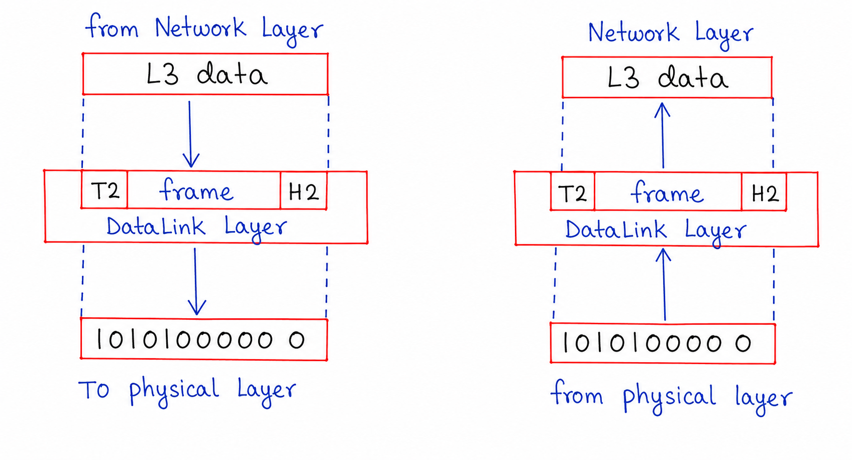
As shown in the diagram, the Data Link Layer receives L3 Data from the Network Layer and encapsulates it into a frame by adding a header (H2) and trailer (T2). The frame is then converted into binary bits and sent to the Physical Layer. At the receiver side, the process is reversed before forwarding the packet to the Network Layer.
Working of Data Link Layer
Sender Side:
- The Data Link Layer receives L3 Data from the Network Layer.
- It encapsulates the packet into a Frame.
- A Data Link Header (H2) is added to the beginning of the frame.
- A Trailer (T2) is added to the end of the frame for error checking.
- The frame contains source and destination MAC addresses.
- The completed frame is converted into a stream of binary bits.
- The data is then transmitted to the Physical Layer.
Receiver Side:
- The Data Link Layer receives binary bits from the Physical Layer.
- The bits are organized back into a frame structure.
- The layer checks the frame for transmission errors.
- The header and trailer information are processed and removed.
- The original L3 Data packet is extracted.
- The packet is then forwarded to the Network Layer.
Functions of Data Link Layer
- Performs framing of network layer packets
- Provides physical addressing using MAC addresses
- Detects transmission errors in frames
- Controls the flow of data between connected devices
- Supports reliable node-to-node communication
- Manages access to the shared communication medium
Key Features
- Framing: Converts packets into frames for transmission.
- MAC Addressing: Uses hardware addresses to identify devices within a local network.
- Error Detection: Detects damaged or corrupted frames using error-checking techniques.
- Flow Control: Regulates data transfer speed between sender and receiver.
- Media Access Control: Determines how devices share and access the transmission medium.
Data Link Layer Sublayers
- Logical Link Control (LLC): Manages communication between upper layers and the Data Link Layer.
- Media Access Control (MAC): Handles device addressing and access to the network medium.
Devices Operating at Data Link Layer
- Switches
- Bridges
- Network Interface Cards (NICs)
Examples of Data Link Layer Protocols
- Ethernet (IEEE 802.3)
- Wi-Fi (IEEE 802.11)
- PPP (Point-to-Point Protocol)
- HDLC (High-Level Data Link Control)
7. Physical Layer
The Physical Layer is the first layer of the OSI Model and serves as the foundation for network communication. It is responsible for carrying data in the form of binary bits through a physical communication channel. This layer focuses on how data is physically transmitted between devices rather than how it is interpreted.
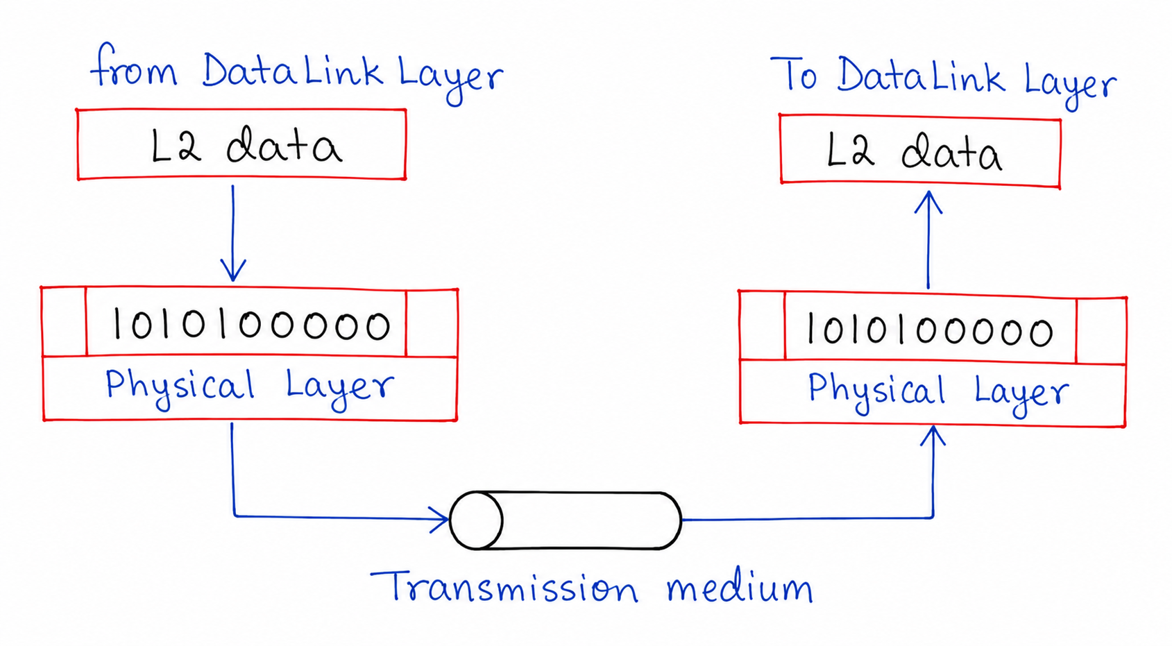
As illustrated in the diagram, the sender's Data Link Layer passes data to the Physical Layer. The Physical Layer converts this data into a sequence of binary bits and transmits them through a communication medium such as a cable, optical fiber, or wireless channel. At the destination, the receiving Physical Layer accepts the incoming bit stream and delivers it to the Data Link Layer for further processing.
How the Physical Layer Works
At the Sender
- Receives data from the Data Link Layer.
- Represents the data as a stream of binary bits.
- Converts bits into physical signals suitable for transmission.
- Sends the signals through the selected transmission medium.
During Transmission
- Signals travel through wired or wireless communication channels.
- The transmission medium carries the bits from the source device to the destination device.
- Different media may use electrical, optical, or radio signals.
At the Receiver
- Receives signals from the transmission medium.
- Converts the signals back into binary bits.
- Reconstructs the original bit stream.
- Forwards the data to the Data Link Layer.
Main Functions of Physical Layer
- Transfers raw bits between network devices.
- Defines signal transmission methods.
- Specifies cables, connectors, and communication interfaces.
- Determines data transmission speed.
- Maintains synchronization between sender and receiver.
- Supports wired and wireless communication technologies.
Key Characteristics
- Bit-Level Communication: Handles only binary data without interpreting its meaning.
- Signal Representation: Converts bits into physical signals for transmission.
- Media Support: Works with various transmission media.
- Transmission Direction: Supports simplex, half-duplex, and full-duplex communication.
- Physical Connectivity: Establishes and maintains physical connections between devices.
Common Transmission Media
- Twisted Pair Cable
- Coaxial Cable
- Fiber Optic Cable
- Radio Waves
- Microwave Communication
- Infrared Signals
Devices Associated with Physical Layer
- Hub
- Repeater
- Modem
- Network Cables
- Connectors and Interfaces
Data Units in OSI Model
| Layer | Data Unit |
|---|---|
| Application | Data |
| Presentation | Data |
| Session | Data |
| Transport | Segment |
| Network | Packet |
| Data Link | Frame |
| Physical | Bits |
Working of OSI Model
When data is sent from the sender, it moves from the Application Layer down to the Physical Layer. During this process, each layer adds its own information (called headers). At the receiver side, the process is reversed, and each layer removes its respective headers to retrieve the original data.
- Sender: Top → Bottom (Encapsulation)
- Receiver: Bottom → Top (Decapsulation)
Advantages of OSI Model
- Standardized communication system
- Easy troubleshooting
- Flexible and modular design
- Supports interoperability
Conclusion
The OSI Model provides a clear understanding of how data flows in a network through its seven layers. Each layer has a specific role, and together they ensure reliable and efficient communication between devices.